Home Page >
Design and Specifications >
Filters
Filters
Mar 24, 2016.
List of Filters
| Band | Arm | λeff (nm) | peak (%) | Δλ(FWHM) (nm) | λ |
λ |
Vendor | Sysmtem | Comments |
|---|---|---|---|---|---|---|---|---|---|
| B | Opt | 443.52 | in prep. | 101.74 | 391.68 | 493.42 | Asahi | Modified Johnson-Cousins | (*1)(*2) |
| V | Opt | 549.14 | in prep. | 107.03 | 495.68 | 602.71 | Asahi | Modified Johnson-Cousins | (*1)(*2) |
| RC | Opt | 653.44 | in prep. | 129.39 | 588.51 | 717.89 | Asahi | Modified Johnson-Cousins | (*1) |
| IC | Opt | 808.79 | in prep. | 138.19 | 739.81 | 877.99 | Asahi | Modified Johnson-Cousins | (*1) |
| Y | Opt | in prep. | in prep. | in prep. | in prep. | in prep. | -- | Original | -- |
| Y | IRA | in prep. | in prep. | in prep. | in prep. | in prep. | BARR | MKO | -- |
| J | IRA | 1248.5 | 89.4 | 159.3 | 1167.8 | 1327.1 | BARR | MKO | (*3) |
| H | IRA | 1638.0 | 97.3 | 286.2 | 1494.0 | 1780.2 | BARR | MKO | (*3) |
| Ks | IRA | 2145.5 | 93.3 | 319.5 | 1986.0 | 2306.4 | BARR | MKO | (*3) |
| H2(v=2→1) | IRA | in prep. | in prep. | in prep. | in prep. | in prep. | in prep. | Original | -- |
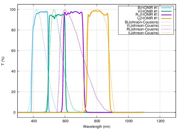
Fig 1: Transmittance curves of optical filters.
Those of Johnson-Cousins system (reproduced by Bessel et al.;
Ref1.;
Ref2.) are also shown as comparison.
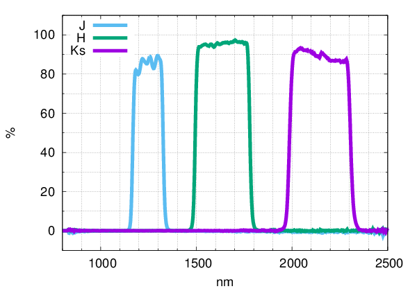
Fig. 2: Transmittance curves of IR filters.
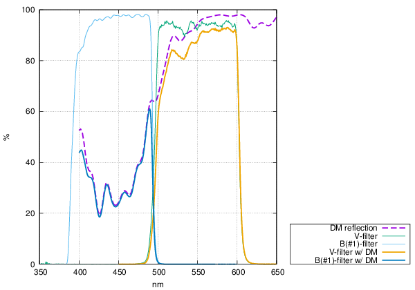
Fig. 3: Effective transmittance curve of B and V filter multiplied by the dichiroic mirror reflectance.